
Jumo211J Engines & Nacelles for Night Fighter
- Lukasz Gmerek

- Dec 5, 2023
- 7 min read
Updated: Jul 30, 2024
In most cases, I proceed to assemble the fuselage immediately after completing the cockpit. I address any issues with mating surfaces, restore lost panel lines and rivets, preparing the aircraft for painting. However, with this particular model, the process diverges. I’m deferring the mentioned steps until several other sub-assemblies are complete.
Those are engine nacelles and the engines themselves. Each nacelle comprises left and right parts, resulting in seam lines at the top and bottom that require removal post-assembly and it will be easier to do when the nacelles are mounted on the fuselage. Additionally I’ve chosen to open inspection hatches on the nacelles, showcasing parts of the Jumo engines, necessitating engine assembly. Moreover, during dry fitting of the nacelles to the underwing mounting points, it became apparent that using putty along certain mating edges would be advisable.
Nacelles

In the initial phase, I removed the sprue attachment points, then proceeded to incorporate PE parts reflecting the ribbing visible in the landing gear bays. Following this, I primed all components, including cowling flaps and nacelles mounting surface underside the wings with Mr. Surfacer 1500 black, followed by RLM02 and a gloss clear varnish. For the nacelle interiors, given their limited visibility, I opted for an efficient approach. The weathering process involved a general oil wash - Black Brown, secured with a layer of satin clear varnish. Quick chipping was executed using weathering pencils (Rubber, Buff, and Aluminum). Shafts & Bearings Grease and Landing Gear washes were then applied around the ribs and blended in when touch-dry. The final touch involved sealing everything with a thin layer of Hataka flat clear.
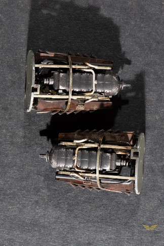
Engines

First, I removed all plastic parts from the sprues for both engines. I opted to enhance the engines and engine nacelles with Eduard’s photo-etched elements. Seizing the opportunity, I cut out all the required PE parts as well. Subsequently, both the plastic and PE components underwent thorough cleaning using sandpaper pads, with particular attention to sprue attachment points.

Regrettably, in 1/48 scale models, it’s common for engine exhaust stabs not to be opened up, and this holds true for this model. Lacking aftermarket resin counterparts, I decided to attempt opening them up using original parts. To achieve this, I utilized a modeling punch to mark the center of each exhaust stab. Then, employing my Proxxon Micromot with a very small diameter drill bit, I created a hole in each stab. I proceeded to remove excess plastic, initially using a sanding pad and then employing extra-thin cement for finer adjustments.
Assembly

Now it was time to assemble the sub-components. However, I’d like to mention one thing before moving forward. In the past, when dealing with components like engines, cockpit, or landing gear, I tended to paint individual elements before assembly. Over time, I realized this approach has drawbacks. The major issue is that if the fit between parts is tight, especially with resin components, painting first may impact it significantly. Applying primer and paint layers could compromise the fit. Additionally, I had to be cautious with glue application to avoid leaving marks on painted parts. Although I initially leaned towards airbrushing everything, I’ve come to understand that certain small elements can be brush-painted without noticeable differences if the right paint and technique are used. While care is needed during painting, this approach is faster and carries fewer risks.

Returning to sub-components, I assembled both engines, added piping to the back bulkhead, and left the rest separate for ease of painting. The assembly also involved photo-etched (PE) parts. Notably, a PE control panel was attached to the side of one engine cantilever, requiring precise bending and gluing. Another set of PE parts, the inspection hatch doors, needed careful bending to match the nacelle’s curvature when mounted in the open position. I used the original parts as a reference for shaping. Several other PE additions were attached following the instructions.
One challenge with the engines from the box is that each main body consists of two parts (left and right), resulting in a visible seam along mating edges after gluing. Instead of purchasing resin counterparts, I opted to use liquid putty to minimize the seam, considering that both engines would mostly be hidden in their nacelles, except for parts visible through opened inspection hatches. While using putty on uneven surfaces isn’t perfect, it proved sufficient in this case.
Painting

I primed all components with Mr. Surface 1500 black. Subsequently, the engines and exhausts were painted in gloss black using Mr. Colour GX2. The rear bulkhead, cantilevers, and other small elements were airbrushed with RLM02 color. I then brush-painted certain engine sub-components with various metallic acrylics (gunmetal, old brass, and silver). Pipes and hoses attached to the back bulkhead were painted NATO Black. Exhausts were airbrushed with metallic Steel, while the front radiators and intake rings received metallic Gun Metal. To complete the painting process, I sealed everything with clear gloss acrylic. The chipping process followed. I used a fine brush and acrylic paints for this step. For the RLM02 elements, I applied a mixture of RML02 and White, followed by another layer of chips using Rubber & Tires color. The engines received subtle chipping with acrylic Silver.
Weathering

I’ll begin with the weathering process for the engines. Initially, I applied Streaking Grime, diluted with an odorless thinner, all over the engines. Using a separate brush, I removed excess and evenly spread the remaining mixture. Subsequently, I applied Shafts & Bearings grease wash to the turbine, especially in the crevices. Once it was dry to the touch, I added another wash to the turbine, this time using Engine and Turbines. Following that, I applied Engine Grime to other metallic parts of the engines. To create contrast, I introduced Dust oil wash into the crevices. A protective layer of Hataka mat clear was applied, and when dry, I performed dry brushing with Gun Metal Drybrush paint and added more chipping with a Silver weathering pencil.

Moving on to the weathering of the rear engine bulkhead, cantilevers, and supporting elements, I initiated the process with a general application of Black Brown oil wash. After a few minutes, I removed excess and blended the rest seamlessly. Next, I crafted a filter using Dark Mud oil paint, significantly diluted with Fast Dry Thinner from Abteilung. The wash was applied to some protruding elements of the rear bulkhead and cantilevers. Subsequently, I performed dry brushing with Medium German Yellow color. Shafts and Bearings Grease wash were then applied to specific areas to simulate increased wear, followed by blending with a flat brush lightly moistened with Odorless Thinner. To conclude the process, I airbrushed a proper layer of matte clear varnish from Hataka. Lastly, I incorporated scratches and scuffs using weathering pencils (Silver, Aluminium, and 70% Gris Chaud).

I initiated the exhausts weathering process with a generous application of Track wash. Subsequently, I allowed it to dry thoroughly for over 12 hours. Using a relatively stiff brush moistened with Odourless Thinner, I then started removing the wash from specific areas. The goal was to create irregular patterns on the surface, considering that the farther aft I worked, the more wash should remain. I left it to dry overnight. In the next stage, I utilized pigments to simulate grime. Initially, I applied Dark Rust pigment by dabbing it onto certain areas, followed by Black pigment on top. Using a stiff brush, I blended the pigments in, with a particular emphasis on applying Black pigment around the exhaust openings to represent soot produced by the engine’s gases and oil. Subsequently, I applied Pigment binder, allowing it to dry. Afterward, I introduced black wash to the exhaust openings to create shadows. Finally, I used an Aluminum weathering pencil along the edges of the exhaust openings.

The weathering process for the front radiators and intake ring commenced with the application of Dust oil wash in the crevices of the radiators. Following this, a layer of flat clear was applied. Once dry, I introduced scratches and scuffs using a Silver weathering pencil. In the subsequent step, I utilized Gun Metal paint to dry brush the protruding elements of the radiators. I then reapplied Dust oil wash. After allowing 15 minutes for drying, I added another layer to the radiators—this time using Industrial Dirt oil wash. Carefully applying this second wash to specific parts of the radiators resulted in a pleasing effect when combined with the previous wash. To conclude this stage of weathering, I applied Earthy Grim wash, focusing this time on the ring itself.
Final Touches

With all sub-components prepared, I began by attaching the cantilevers to the engines and then joined them together with the aft bulkhead. Subsequently, I airbrushed a thin layer of satin clear varnish over the just-assembled components. In the following step, I dry-fitted the exhausts and carefully checked the engine’s fitting into the nacelles. It became apparent that the engine fit nicely, but I encountered an issue with the front radiator ring. First I had to trim the exhausts slightly and in the next step I had to increase a bit size of the opening of the ring. Only then the ring snapped nicely onto the engine hub.

Given that parts of the engines would be clearly visible with the inspection hatches opened, I decided to enhance the look by adding additional cabling. For this, I utilized Soft Pipes 0.6 and black wire 0.4. Using tweezers, I delicately guided the pipes between the cantilevers and the engine, and the wire was cut in half, woven together, and similarly guided through. To secure the cables, I applied CA glue in a few discreet, hidden places. I revisited the use of Shafts & Bearings Grease and Engine Grime washes in specific areas to emphasize usage and dirt even further.

Fitting engines into the nacelles

The first step was to attach the side of the engine without the compressor to the nacelle. To achieve this, I coated the mating surface of the back bulkhead with CA glue and then pressed it against half of the nacelle. Subsequently, I added the front radiator ring, once again utilizing CA glue. It's crucial to be meticulous during this step, considering the position of the radiators in relation to the nacelle and the engine hub. Afterward, I connected it to the second half of the nacelle. During this process, I only applied glue to the second half of the ring and the front top part of the nacelle's halves. The remaining mating surface was intentionally left unglued, which will prove beneficial when mounting the nacelles onto the fuselage. Only after this step will I proceed to glue both sides of each nacelle together.
Closing Words

It took considerable effort and time to elevate those engines to such a level, but the results are truly rewarding. The fact that they are mostly concealed within their respective nacelles doesn't bother me in the least. I can always refer to the photos, and the experience gained makes the effort truly worthwhile.
As always, if you have any questions or feedback, please leave a comment below. And, of course, you can always browse through the photos in the gallery, dear reader. Until the next one


Comments